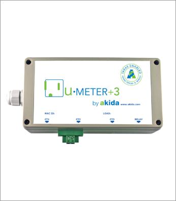
u.METER+3
The u-METER+3 is our three-phase option for our remote, wireless Monitor node. It has to be attached to the power supply of the load/circuit being monitored with a four-wire cord. The unit also has three external CT coils that have to be installed around each phase of the wiring for the circuit or load to be monitored. The u-METER+3, is designed to be installed in parallel to a load with no electrical connectivity wherein the high amperage load does not run through the unit. It is connected to the same 110V-250V circuit being monitored so that it can continuously monitor the voltage in the circuit. There is a very small power draw for the low voltage electronics. The unit is housed in a UL rated plastic enclosure and contains a digital, monitoring, analysis and communication system. The unit has connectors for leads from external CT coils for monitoring-signals. This unit is strictly for true three-phase monitoring of electrical parameters at a highly granular level. The unit has an on-board FCC compliant radio to provide data via a wireless network and can also be paired wirelessly to other Akida hardware.
HOW THE u-METER+3 WORKS
Overview
The product uses three external current transformers (CT1, CT2 and CT3) to detect and monitor the electricity in the power cables of the existing circuit. The CT has to be appropriately selected from our range of calibrated CTs, based on the amperage rating of the circuit. The on board TARAS digital energy metering cards are able to provide real-time data on more than fifty parameters for electricity. This data is then relayed using RF wireless frequency of 2.4GHz to a remote Energy Gateway processor in an EMP or a Control Server. With detailed data on the quality of the electrical power from the grid, maintenance schedules can be adjusted to maintain efficiency. Catastrophic failure of expensive, high-power equipment can be mitigated, by looking for anomalies in the data.
-
Data Sheet
.pdf download link will be here soon -
Installation Guideline
.pdf download link will be here soon -
Wiring Diagram
.pdf download link will be here soon -
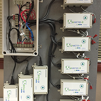
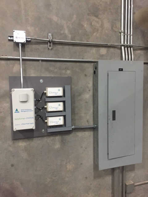
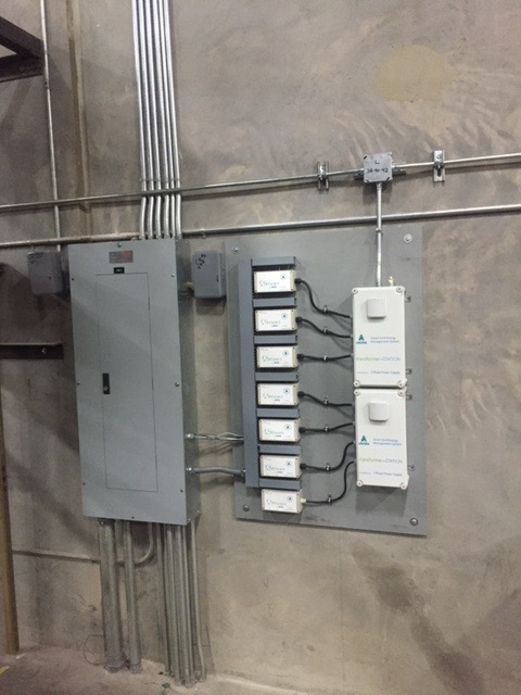
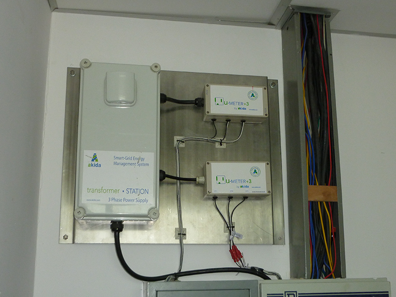
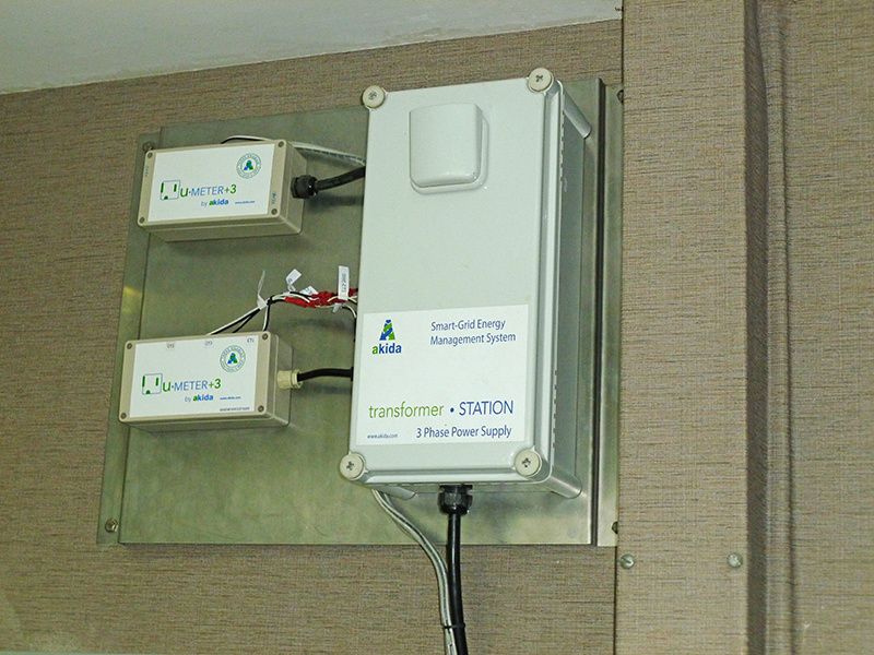
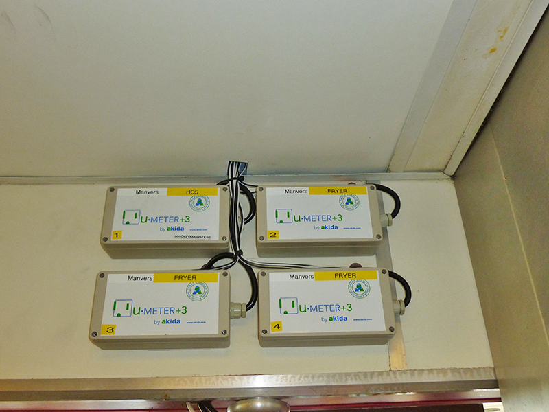
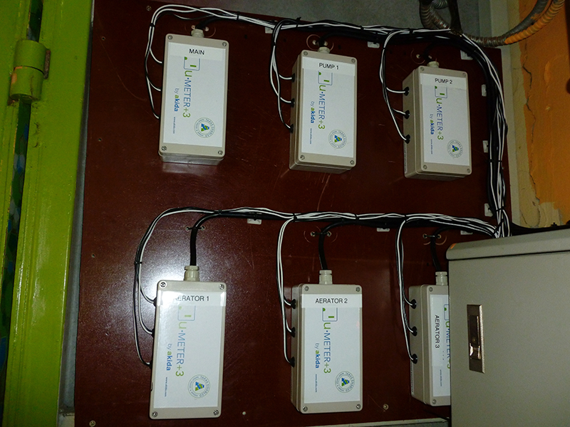
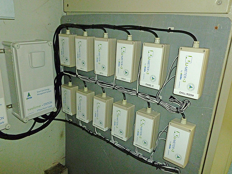
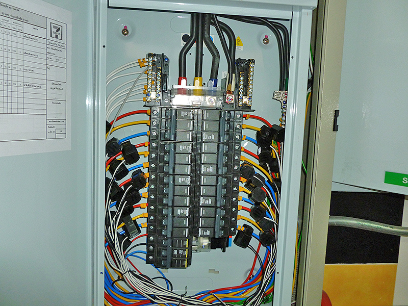
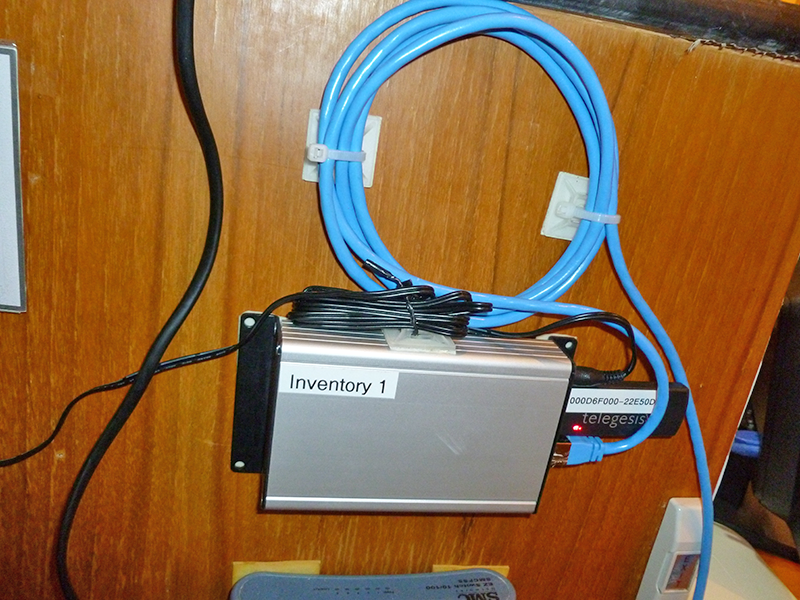
Installation Photos